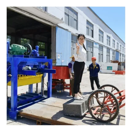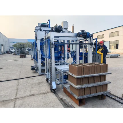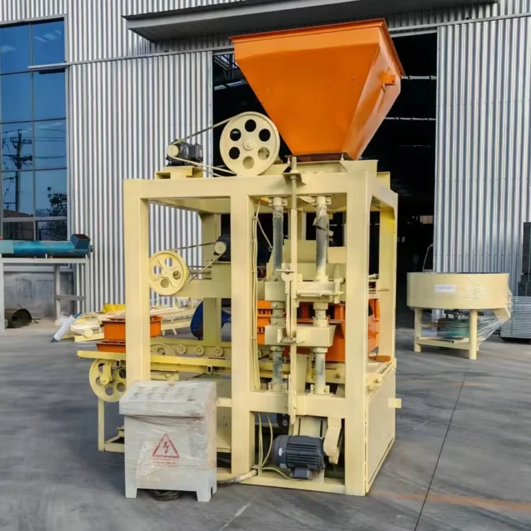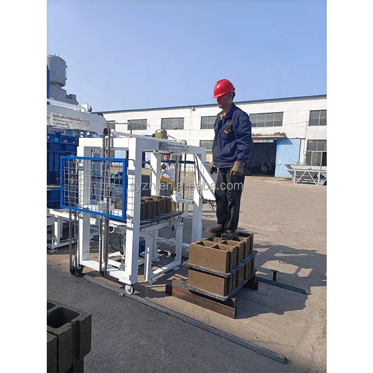




Description
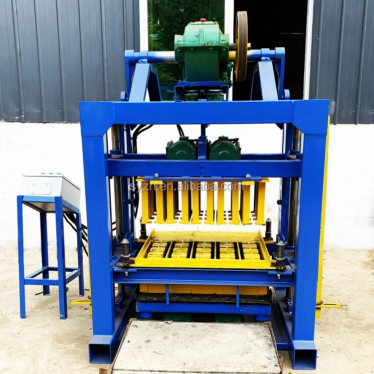
Intelligent Control Matching — The QTF3-20 automatic stationary block machine PLC controlled configuration is built around the operator’s language and voltage environment, not just the press output.
Technical Specifications
| Parameter | Value |
|---|---|
| Model | QTF3-20 |
| Product Type | Stationary Concrete Block Making Machine |
| Overall Dimensions (L×W×H) | 4000×3500×2300 mm |
| Net Weight | 2870 kg |
| Total Power | 17.5 kW |
| Control Style | Semi-Automatic (PLC-based) |
| Vibration Form | Platform Vibration |
| Host Frame | #12 U-bar welded structure |
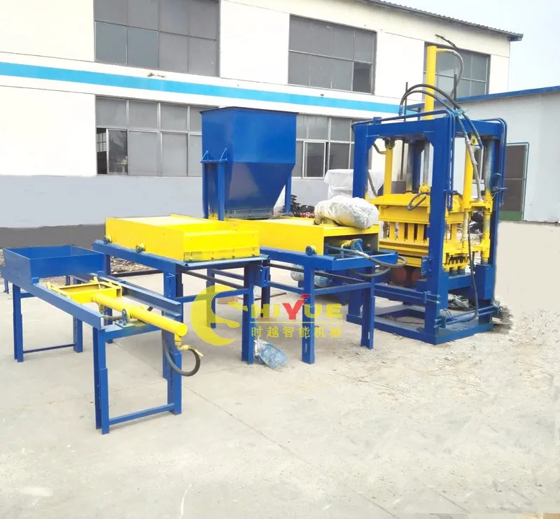
| Double Layer Feeding | Yes |
| Proximity Switch | No-contact type |
| Output Capacity | 4320 pcs/day (basis not stated in source — confirm block format) |
Application Suitability
| Application | Material or Output |
|---|---|
| Hollow block production | Cement, sand, coarse aggregate, fly ash |
| Color paver and interlock brick | Base mix with color surface layer (double feed) |
| Grass and slope protection brick | Cement and aggregate with porous structure |
| Standard and porous solid block | Slag, fly ash, sand, and cement blends |
What the PLC Panel Language Costs You on Day One
An automatic stationary block machine PLC controlled setup that ships in the wrong HMI language stalls production before the first cycle runs.
I once walked onto a site where the mason spent an entire shift staring at Chinese fault codes on a touchscreen nobody thought to specify in English. The translator flight cost more than the panel upgrade would have. With the QTF3-20, the control stack is locked to your operator’s language and local voltage before the crate closes in Shandong [NEED_CITE: HMI language requirements for exported industrial machinery]. Commissioning delays trace back to assumptions made at the order stage, not the machine itself.
From Semi-Automatic to Full Line Automation
The QTF3-20 ships in a semi-automatic control style, meaning the operator still handles pallet movement and stacking at the line ends. This is deliberate: it keeps the initial investment contained while the press, mixer, and feeder learn your mix design. The automatic stationary block machine PLC controlled architecture leaves headroom for adding automatic pallet feeding, stacking, and cubing as volume grows, without replacing the host machine or rewriting the control logic.
Double-Layer Color Feeding in a Single Cycle
Producing color pavers requires a base layer of standard mix topped with a thin pigmented surface. The QTF3-20 integrates a color material machine alongside the primary feeder, so both layers deposit into the mould in one press cycle. This eliminates a separate facing pass, keeps the color coat thickness consistent across batches, and removes the operator variable that typically causes shade drift between morning and afternoon runs [NEED_CITE: concrete paver facing layer consistency standards].
Pressure, Vibration, and What Density Actually Depends On
Platform vibration compacts the mix from below while the hydraulic press foot applies downward force. On the QTF3-20, these two systems must be balanced against your specific aggregate size and cement ratio. A coarse local crushed stone needs higher vibration amplitude and longer dwell than fine river sand. The #12 U-bar welded frame absorbs the reaction force so the vibration energy goes into the block, not into shaking the machine apart. Total power draws 17.5 kW across the vibration motors, hydraulic pump, and feeder drives — a figure that determines your transformer sizing and dedicated circuit planning back at the plant.
The Commissioning Delay Nobody Budgeted For
When voltage and frequency are assumed rather than confirmed, the PLC transformer and motor contactors arrive mismatched to the local grid. The QTF3-20 draws 17.5 kW, so running it on an undersized generator or a 50Hz supply wired for 60Hz motors means overheated windings by the end of the first week [NEED_CITE: voltage and frequency standards by export market]. Locking the electrical schematic to your site power before production begins avoids rewiring the control cabinet on the shop floor.
Why Sourcing the Control Stack Here Is Different
The machine, mould, pallet, and handling equipment are specified as one matched system, so the PLC inputs align with the actual sensors on your line. Configuration is set against your local aggregate and target block format rather than a catalogue default. Mould drawings arrive before the machine ships, so you can verify format changeover steps against your production schedule. Electrical schematics list component origin, meaning your maintenance team knows which hydraulic valve and proximity switch to reorder. The automation level is selectable, letting you start semi-automatic and add stacking or cubing stations later without a control system overhaul.
Documentation & Verification
- Line layout and capacity calculation naming the block format behind the daily output figure
- Hydraulic and electrical schematic with component origin for spare part sourcing
- Voltage, frequency, and PLC display language confirmation sheet signed before dispatch
- Factory test record run on your specified mix design and block format
- Mould drawing and format list covering hollow, interlock, paver, and grass brick options
Installation, Commissioning & Support
- Dedicated 17.5 kW circuit with correct voltage and frequency confirmed before the QTF3-20 arrives on site
- Foundation plan sized to the 4000×3500 mm footprint and platform vibration load
- Host machine, feeder, hydraulic station, and electricity box arrive dismantled for container loading
- PLC parameter tuning and proximity switch calibration performed during first-day commissioning
- No-contact proximity switch type reduces adjustment wear during high-cycle operation
- Operator training covers mould change procedure, double-layer feed setup, and fault code reading
What to Include in Your Inquiry
Send the block format you plan to run most days, your local aggregate type and maximum particle size, and the daily output target tied to that specific format. Confirm your site voltage, frequency, and preferred PLC display language. If you already have a mixer, pallets, or a curing rack system, share those specifications so the QTF3-20 line configuration matches your existing equipment.
Frequently Asked Questions
Q: How is the 4320 pcs/day output verified and which block format does it assume?
A: That figure appears in the source data without a stated block format, material mix, or cycle time. Before ordering, request a capacity calculation sheet that names the exact block size and wall thickness used for the estimate, so you can compare it against your actual product range and daily targets.
Q: What automation upgrades are available from the current semi-automatic configuration?
A: The PLC architecture supports adding automatic pallet feeding, stacking, and cubing stations as separate modules. The host machine and control cabinet remain in place; you extend the line outward. This path lets production volume justify each automation investment rather than paying for full automation before demand requires it.
Q: How is vibration force and hydraulic pressure matched to my local aggregate?
A: The platform vibration amplitude and hydraulic press foot pressure are adjusted based on your mix design and coarse aggregate size. A trial run with your actual material confirms block density before the machine ships, so the settings arrive pre-tuned rather than requiring weeks of adjustment on your floor.
Q: What voltage, frequency, and PLC language options are confirmed before dispatch?
A: The electrical schematic is built around your site’s specific supply. The PLC HMI language is set to your operator’s requirement — English, Spanish, Arabic, or other — and confirmed in writing before the control cabinet is closed, eliminating commissioning-day translation delays.
Q: What is the mould change procedure and how long does a full format changeover take?
A: The QTF3-20 supports hollow, interlock, paver, and grass brick moulds on the same host. The mould drawing package includes a step-by-step changeover procedure listing the up mold cylinder, press foot, and mold box removal sequence. Request the estimated changeover time for your specific format pair so you can plan shift scheduling around it.