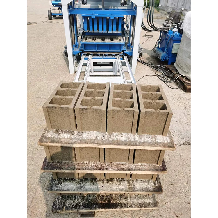


Description
Integrated PLC Automation — every pallet feed, press cycle, and sweep sequence on the QT4-15A is governed by a single programmable logic controller rather than split across independent relays, eliminating the timing mismatches that stall semi-automatic lines.
Technical Specifications
| Parameter | Value |
|---|---|
| Model | QT4-15A |
| Product Type | Fully Automatic Concrete Block Production Line |
| Overall Dimensions (L×W×H) | 7100×1600×2610 mm |
| Total Weight | 3 T |
| Molding Cycle | 15–25 s |
| Vibration Frequency | 4600 r/min |
| Vibration Force (Exciting Power) | 40–50 kN |
| Total Power | 18.45 kW |
| Mixer Model | JQ350 |
| Pallet Size | 850×550×25 mm |
| Control System | PLC control system |
| Hydraulic Station | High-pressure hydraulic system included |
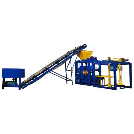
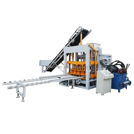
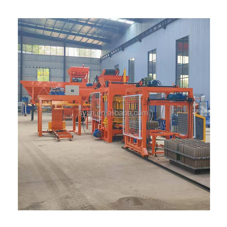
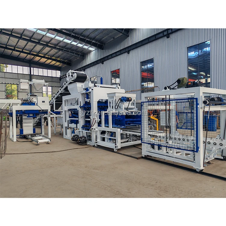
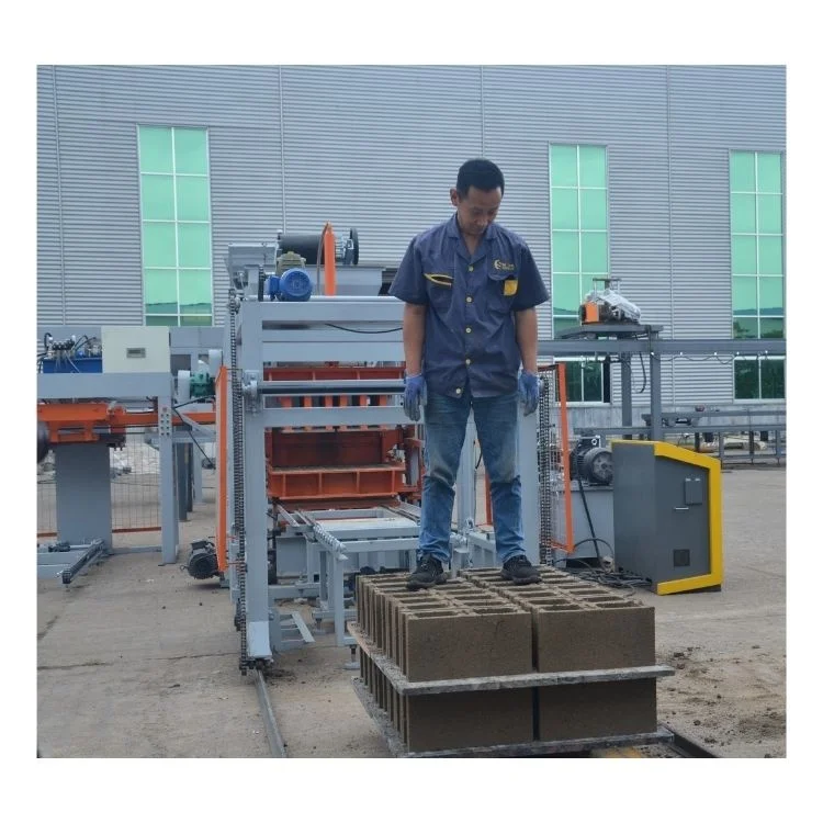
| Line Components | Block making machine, hydraulic station, PLC control cabinet, pallet feeder, brick conveyor, block sweeper |
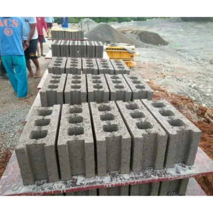
| Applied Products | Hollow block, solid brick, paver, curbstone |
| Output — Hollow Block 400×200×200 mm | 4 pcs/mould, 408 pcs/h, 3264 pcs/8 hr |
| Output — Hollow Block 400×150×200 mm | 5 pcs/mould, 510 pcs/h, 4080 pcs/8 hr |
| Output — Solid Brick 240×115×53 mm | 18 pcs/mould, 2100 pcs/h, 17000 pcs/8 hr |
| Voltage & Frequency | To be confirmed before production |
| PLC Display Language | To be confirmed before production |
| Stacking Method | To be confirmed (manual or automatic) |
Application Suitability
| Application | Material or Output |
|---|---|
| Hollow block production for load-bearing walls | Crushed stone, sand, cement, fly ash blends |
| Solid brick manufacturing for partition walls | Fine aggregate and cement mixes |
| Interlocking paver runs for municipal walkways | Pigmented concrete with coarse aggregate |
| Kerbstone extrusion for road edging | High-strength concrete with graded stone |
Why the PLC Language Question Matters Before You Sign the Contract
A programmable controller is only intelligent when the operator can read it.
Too many automatic block production line PLC controlled installations arrive on site with the HMI locked to a default language the local crew cannot read. I once spent hours on a call at four in the morning walking a technician through a menu tree in a language his operators did not recognize, just so the line could run its first cycle. The QT4-15A control interface language must be confirmed in writing before the cabinet is wired, along with the voltage and frequency rating for the destination market. Skipping that step turns a fully automatic line into a very expensive manual press [NEED_CITE: PLC display language requirements for export machinery].
How the Control Loop Keeps Cycle Timing Honest
On this line, the PLC governs every station from pallet indexing through mould filling, vibration, hydraulic pressing, and block sweeping. When one station lags, the controller holds the upstream sequence instead of dumping a half-pressed pallet onto the conveyor. That coordination is what separates an automatic block production line PLC controlled setup from a collection of individual machines pretending to be a line. The molding cycle of 15–25 seconds holds only because the pallet feeder, press, and sweeper are timed to a single program, not to independent timers that drift apart over a shift.
What Full Automation Actually Removes from the Operator
With the integrated pallet feeder, brick conveyor, and block sweeper, the operator’s role shifts from loading and moving to monitoring and quality checking. The automatic block production line PLC controlled architecture handles the repetitive transfer work that causes fatigue-related defects in semi-automatic plants. Vibration force and hydraulic pressure remain constant across every cycle because the PLC triggers them at fixed set-points rather than relying on an operator judging when the mould looks full enough. Consistency in block density and dimensions comes from removing the human timing variable, not from adding more sensors [NEED_CITE: automation impact on block density consistency].
Reading the Numbers Behind the Vibration and Hydraulic Specs
The 4600 r/min vibration frequency paired with 40–50 kN of exciting power is tuned for the 850×550 mm pallet area and the mould formats listed. If the vibration were higher without matching hydraulic clamping force, the mix would liquefy and bleed water; too low and the block leaves the mould with weak edges. The high-pressure hydraulic station delivers the clamping force needed to hold the mould rigid during vibration, which is what gives hollow blocks their wall thickness tolerance and solid bricks their compressive strength. The 18.45 kW total power figure includes the mixer motor, hydraulic pump, and vibration motors running simultaneously, so your site supply must account for starting surge above that rated value. The JQ350 mixer feeds at a rate matched to the 15–25 second molding cycle so the press hopper never starves between cycles.
The Hidden Cost of Leaving Automation Gaps in the Line
Buyers often configure the press and pallet feeder but leave stacking and curing rack handling as manual tasks, then wonder why daily output never reaches the quoted figures. When operators are pulling heavy wet pallets off the conveyor by hand, fatigue sets in by mid-shift and the rhythm breaks. The automatic block production line PLC controlled system is designed to keep the press cycling, but if the downstream stations cannot keep up, the PLC will hold cycles and throughput drops. Stacking method, curing rack capacity, and forklift availability must be settled during line design, not after the containers arrive [NEED_CITE: block plant line balancing principles].
Why Procurement Through This Channel Reduces Commissioning Risk
Every QT4-15A leaves the factory with a documented voltage, frequency, and PLC language confirmation because those details are locked before the electrical cabinet is assembled. The line layout and capacity calculation state the block format behind each output figure so there is no ambiguity about what 3264 hollow blocks per eight-hour shift actually assumes. Mould drawings and format lists ship with the machine, meaning your maintenance team can plan changeover procedures before the line is bolted down. Hydraulic and electrical schematics are provided in full, not as simplified diagrams, so local electricians can trace faults without waiting for a remote support call. Configuration is set against your actual mix design and local aggregate, not a catalogue default that forces you into material substitutions.
Documentation & Verification
- Line layout showing pallet flow from feeder through sweeper to stacking area
- Capacity calculation per block format with cycle time assumptions stated
- Hydraulic and electrical schematic with circuit references for site troubleshooting
- PLC program version and HMI language locked in writing before dispatch
- Factory test record on your target block format before container loading
- Mould drawing and format list for changeover planning
Installation, Commissioning & Support
- Foundation pad must accommodate 7100 mm length with clearance for pallet feeder and conveyor
- Dedicated circuit rated above 18.45 kW continuous draw with starting surge allowance
- PLC cabinet tested on confirmed voltage and frequency before cabinet sealing
- Operator training covers HMI navigation, alarm response, and mould change procedure
- Wear parts list and hydraulic seal kit included for first maintenance interval
- Pallet size 850×550×25 mm confirmed against your curing rack spacing and forklift capacity
What to Prepare Before Requesting a Quotation
Share the block formats your market actually sells along with target daily output per format, so the cycle time calculation is built around real products. Confirm the voltage, frequency, and preferred PLC display language for your site so the control cabinet is wired correctly on the first build. Let us know your existing pallet dimensions and curing area layout to verify that the 850×550 mm pallet fits your handling infrastructure without modification.
Frequently Asked Questions
Q: How is output capacity verified per block format on this line?
A: Each capacity figure is tied to a specific block size and mould cavity count. For example, 400×200×200 mm hollow blocks run at 4 pcs per mould, yielding 408 pieces per hour based on the stated molding cycle. The calculation assumes continuous operation with the pallet feeder and conveyor keeping pace. Any deviation in mix consistency or manual intervention downstream will reduce actual throughput from that baseline.
Q: What automation components are included and where can the line be expanded?
A: The QT4-15A ships with a pallet feeder, brick conveyor, block sweeper, and PLC-controlled press cycle. Stacking and cubing systems are configurable based on your plant layout and budget. If you start with manual stacking, the PLC program can be updated later when an automatic stacker is added, without replacing the main controller.
Q: How are voltage, frequency, and PLC language confirmed before shipment?
A: These three parameters are confirmed in writing during the order stage and locked before the electrical cabinet is assembled. The PLC program is flashed to the confirmed language version, and the transformer and motor ratings are matched to the destination grid. A pre-dispatch test runs the full cycle on the confirmed voltage setting.
Q: How is the vibration and hydraulic pressure matched to our local aggregate?
A: Your mix design and aggregate gradation are collected during the inquiry stage. The vibration frequency of 4600 r/min and the hydraulic clamping pressure are then set to compact that specific mix without segregation. If your aggregate differs significantly from standard sand and crushed stone, a trial run is recommended before final settings are locked.
Q: What is the mould change procedure and how long does it take?
A: The mould is bolted to the vibration table and connected to the hydraulic clamping frame. Changeover involves releasing the clamps, lifting the current mould, positioning the new one, and re-securing all connections. The exact time depends on the format difference and whether the operator has the mould drawing for reference. Detailed changeover procedures are provided per mould set.