Description
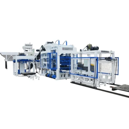
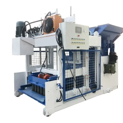
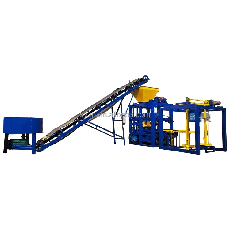
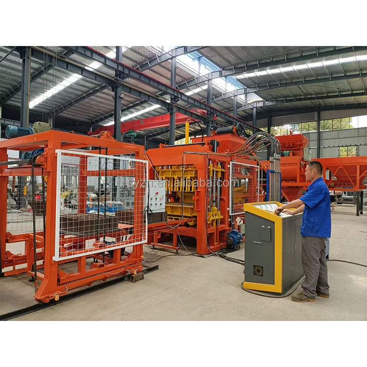
Intelligent control integration — The automatic QT6-15 block making machine PLC controlled system removes operator guesswork through fault diagnosis logic and action interlock safety, ensuring each moulding cycle executes within set parameters regardless of shift changes or operator experience level.
Technical Specifications
| Parameter | Value |
|---|---|
| Model | QT6-15 |
| Product Type | Automatic Hydraulic Block Making Machine |
| Overall Dimensions (L×W×H) | 8200×1700×2950 mm |
| Total Mass | 7 T |
| Overall Power | 37 kW |
| Control System | PLC with touch screen HMI, integrated fault diagnosis |
| Vibration Form | Platform Vibration |
| Vibration Frequency | 0-60 Hz (adjustable) |
| Vibration Force | 45 kN |
| Moulding Mode | Automatic loading, vibration moulding |
| Demolding Method | Hydraulic |
| Molding Cycle | 15-20 s (basis to be confirmed by block format and material) |
| Pallet Size | 880×850 mm |
| Recommended Factory Area | 1200 m² |
| Hydraulic System | Independent integrated hydraulic station |
| Output – Hollow Block 400×200×200 mm | 1080-1440 pcs/h, 8640-11520 pcs/8hr (based on 15-20s cycle) |
| Output – Hollow Block 400×150×200 mm | 1440-1920 pcs/h, 11520-15360 pcs/8hr (based on 15-20s cycle) |
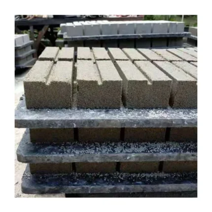
| Output – Solid Brick 240×115×53 mm | 5760-7680 pcs/h, 46080-61440 pcs/8hr (based on 15-20s cycle) |
| Output – Rectangular Paver 200×100×60 mm | 2160-2880 pcs/h, 17280-23040 pcs/8hr (based on 20-25s cycle) |
| Block Compressive Strength | >15 MPa (source value — verify against specific mix design) |
| Automation Level | High (PLC process control, automatic loading, touch screen interface) |
| Warranty | 1 year for whole machine excluding spare parts |
Application Suitability
| Application | Material or Output |
|---|---|
| Hollow block production for building walls | Crushed stone, sand, cement, and waste ash blends |
| Solid brick production for masonry | Standard aggregate mixes and slag-based materials |
| Rectangular and zigzag paving block production | Fine aggregate with cement for road and walkway surfaces |
| Block plants utilizing industrial by-products | Waste ash, slag, and various locally sourced aggregates |
| Construction contractors producing on-site | Mobile or fixed plant setups with local raw material supply |
| Building material manufacturers expanding format range | Multiple mould configurations for hollow, solid, and paver formats |
Why Automation Level Matters More Than Cycle Time Alone
A quoted cycle time means nothing if the operator must manually intervene between every step.
The automatic QT6-15 block making machine PLC controlled architecture addresses a problem I have watched play out repeatedly on production floors: the gap between what a machine can do in a factory test and what it actually delivers during a ten-hour shift with changing operators. When pallet feeding, material loading, and vibration sequences depend on manual timing, the real cycle stretches well beyond the rated figure. [NEED_CITE: impact of manual intervention on actual block machine cycle times] The PLC with touch screen HMI on this press stores process parameters for each block format, so switching from hollow blocks to pavers does not require the operator to relearn timing by trial and error.
How PLC Logic Reduces Shift-to-Shift Variability
Every block plant I have commissioned faces the same pattern: the morning crew runs the machine one way, the afternoon crew adjusts parameters based on feel, and by evening the block strength readings scatter across a wide range. The fault diagnosis system integrated into the QT6-15 control architecture addresses this directly. When a sensor detects a sequence deviation — a pallet not fully seated, a vibration cycle cut short — the action interlock logic halts the cycle rather than producing a substandard block. This is not about replacing the operator; it is about giving the operator a system that refuses to run outside its configured boundaries. The automatic QT6-15 block making machine PLC controlled setup stores the vibration frequency, moulding pressure, and cycle duration for each format, so the machine performs identically whether it is the first shift or the third.
What the Independent Hydraulic Station Actually Solves
Hydraulic systems mounted directly on the main frame of a block press absorb vibration with every cycle. Over weeks of production, this exposure degrades valve seals and accelerates hose fatigue. [NEED_CITE: hydraulic component failure rates in vibrating machinery environments] The QT6-15 separates its hydraulic station from the press body entirely. The independent integrated station sits isolated from platform vibration and dust ingress, which means the demolding system maintains consistent pressure delivery across the production run. When I adjusted parameters on a Middle East site last year, the hydraulic response remained stable through hundreds of consecutive cycles — something that would not have held up with an integrated unit taking direct vibration loads.
Reading the Specification Sheet Against Your Actual Production Needs
The vibration frequency range of 0-60 Hz and the 45 kN vibration force are not abstract numbers; they determine whether your local aggregate will compact properly inside the mould. Different materials respond to different frequencies — fine sand needs higher frequency with lower amplitude, while coarse crushed stone requires lower frequency with higher force transmission. The platform vibration system on the QT6-15 allows the operator to dial in the frequency that matches the mix design rather than accepting a factory default. The 880×850 mm pallet size must also be evaluated against your existing curing area dimensions and forklift capacity. A pallet that does not match your racking system creates a bottleneck downstream of the press itself. The 37 kW overall power draw requires a dedicated circuit with appropriate breaker sizing, and the voltage and frequency must be confirmed to match your local grid before production begins.
When the Wrong Automation Choice Costs You Output
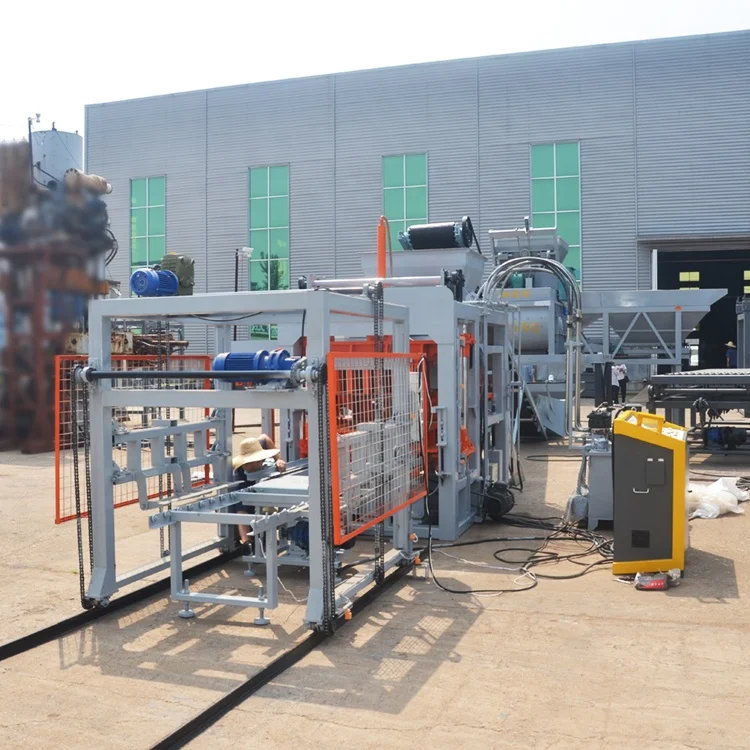
I have seen block plant owners invest in a press with strong cycle time ratings, only to discover that the pallet handling, stacking, and curing steps were not part of the quotation. The result is output stacked by hand at the end of the line, with workers moving wet blocks to curing racks at a pace that cannot match the press output. The bottleneck simply shifts from the machine to the manual handling stations. [NEED_CITE: production bottlenecks in block plants from incomplete line configuration] The automatic QT6-15 block making machine PLC controlled system addresses the press-side automation, but the buyer must also confirm whether automatic stacking and pallet return are included in the line layout. Without that confirmation, the daily output figures in the specification table represent a theoretical maximum that the surrounding manual processes cannot sustain.
What Sets This Configuration Apart
Block machinery is the single focus here, which means the press, mould, pallet, and handling equipment are specified as one matched system rather than assembled from separate suppliers. The QT6-15 configuration is set against your actual mix design and local aggregate, not a catalogue default that assumes ideal materials. Mould design covers the formats your market actually sells, including custom drawings when standard sizes do not match local building codes. The automation level is selectable, so a buyer starting with semi-automatic pallet handling can upgrade the line as production volume grows. Installation support includes on-site commissioning and operator training, ensuring the PLC parameters are validated with your specific raw material before the machine enters full production. [NEED_CITE: block machine commissioning requirements for different aggregate types]
Documentation & Verification
- Line layout with capacity calculation stating the exact block format assumed for each output figure
- Hydraulic and electrical schematic with fault diagnosis parameter list for your local maintenance team
- Voltage, frequency, and PLC display language confirmation document signed before production starts
- Mould drawing and format list showing which block sizes are included and the changeover procedure
- Factory test record run on your specified raw material blend before dispatch
- Operation and maintenance manual with wear parts list and recommended replacement intervals
Installation, Commissioning & Support
- Foundation pad sized for the 8200×1700 mm footprint with vibration isolation considerations for the 7 T operating mass
- Dedicated power circuit rated for the 37 kW overall load with voltage and frequency matching your local grid supply
- Main press arrives fully assembled; supporting line equipment configured and installed based on confirmed layout
- PLC parameters calibrated to your raw material during on-site commissioning with test production runs
- Operator training covering touch screen HMI navigation, format changeover, and fault diagnosis response procedures
- Wear parts and mould maintenance schedule established during commissioning with local supply chain verification
Before You Request a Quote
To configure the automatic QT6-15 block making machine PLC controlled system for your production line, we need to know which block formats you intend to produce and the daily volume target for each. Send a sample of your local aggregate — sand, crushed stone, ash, or slag — so the vibration parameters can be matched to your actual material. Confirm your local voltage, frequency, and preferred PLC display language. If you have an existing curing area and forklift, share the dimensions so the 880×850 mm pallet specification can be validated against your downstream handling setup.
Frequently Asked Questions
Q: How is the QT6-15 output capacity verified per block format, and what cycle time does each format require?
A: Each output figure in the specification table is tied to a specific block dimension and its corresponding moulding cycle. Hollow blocks at 400×200×200 mm run on a 15-20 second cycle, while pavers at 200×100×60 mm require 20-25 seconds due to higher compaction density. The capacity calculation document provided with your quotation states the exact format and cycle time assumed, so there is no ambiguity between quoted output and actual production.
Q: What PLC control language and HMI interface options are available, and are they confirmed before shipment?
A: The PLC display language is confirmed during the quotation stage and locked before production begins. The touch screen HMI supports multiple language options to match your operator team. A confirmation document listing the selected language, voltage, and frequency configuration is signed by both parties, preventing commissioning delays caused by interface language mismatches after the machine arrives at your facility.
Q: How does the automation level affect operator count, and what is the upgrade path from semi-automatic?
A: The high automation configuration handles loading, vibration moulding, and demolding through PLC-controlled sequences, reducing the manual intervention points per cycle. Plants upgrading from semi-automatic operation typically start with manual pallet handling and add automatic stacking and pallet return as production volume increases. The QT6-15 control architecture supports these additions without requiring a full system replacement.
Q: What voltage and frequency configurations are supported, and how is this confirmed for the target market?
A: The electrical system is configured to match the buyer’s local grid specifications, which must be confirmed before production starts. The quotation process includes a voltage and frequency verification step that accounts for your site’s power supply characteristics. This prevents the common problem of a machine arriving with a motor or control system that does not match the local electrical infrastructure.
Q: How does the independent hydraulic station improve reliability compared to integrated hydraulic systems exposed to vibration?
A: The QT6-15 hydraulic station is physically separated from the main press frame, isolating valves, seals, and hoses from the platform vibration generated during each moulding cycle. This separation reduces component fatigue and extends service intervals compared to systems where hydraulic elements are bolted directly to the vibrating structure. Maintenance access is also improved since the station sits outside the press enclosure.