

Description
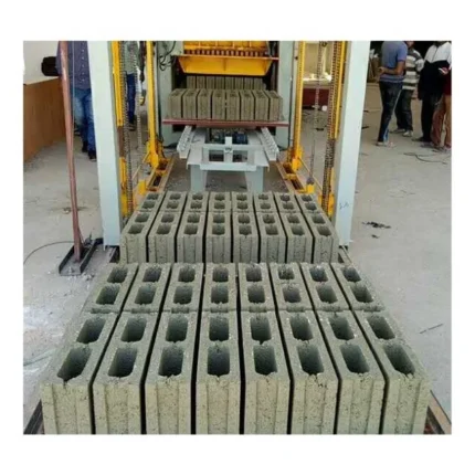
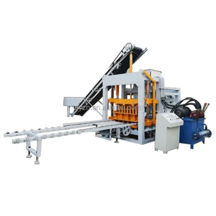
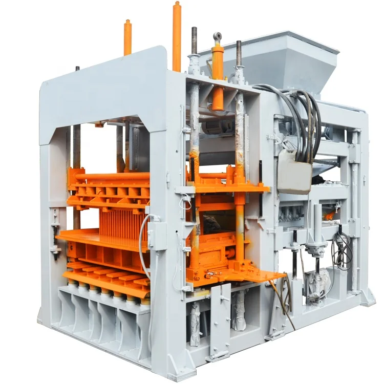
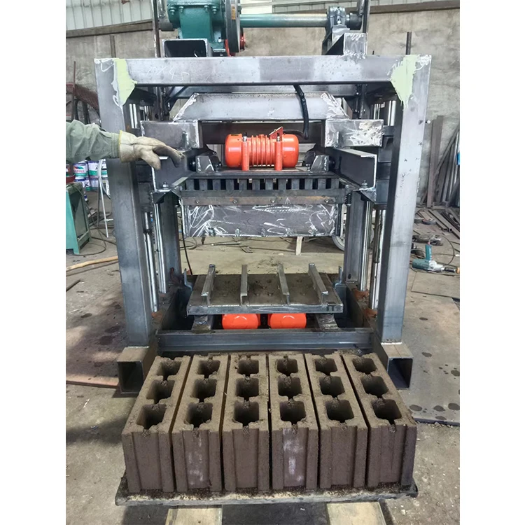
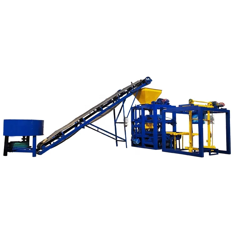
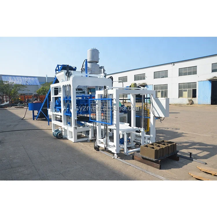
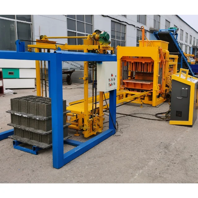
Hydraulic-PLC Integration — The automatic QT4-15A block making machine pairs 16–21 MPa rated pressure with 55 KN vibration force, calibrated to your local aggregate and target format rather than a default catalogue setting.
Technical Specifications
| Parameter | Value |
|---|---|
| Model | QT4-15A |
| Product Type | Hydraulic Concrete Block Making Machine |
| Overall Dimensions | 4100 × 1600 × 2600 mm |
| Rated Pressure | 16–21 MPa |
| Main Vibration Form | Platform Vibration |
| Vibration Frequency | 4200 r/min |
| Vibration Force | 55 KN |
| Pallet Size | 880 × 550 mm |
| Molding Cycle | 25–30 s per pallet (basis not stated in source — confirm block format / material / thickness) |
| Overall Power | 18.45 kW (source value — verify against manufacturer catalog) |
| Total Mass | 4 T |
| Demolding Method | Hydraulic |
| Factory Area | 300 m² |
| Control System | PLC-controlled block machine |
Application Suitability
| Application | Material or Output |
|---|---|
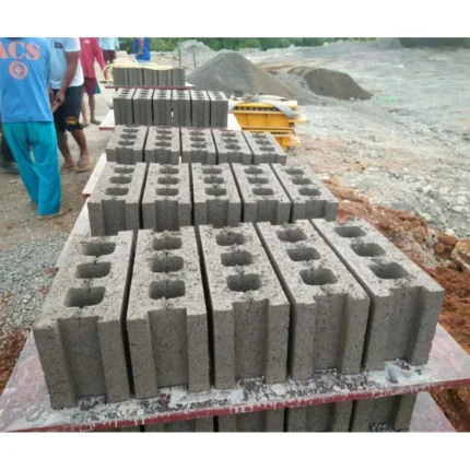
| Hollow block production | Crushed stone, sand, cement, fly ash |
| Solid block manufacturing | Gravel, slag, cement blends |
| Paving block pressing | Dense aggregate mixes with pigment additives |
| Interlocking brick forming | Low-slump concrete with fine sand |
| Curbstone and kerb production | Coarse aggregate with high cement ratio |
What a PLC Controlled Block Machine Actually Removes from the Operator
Consistency that manual timing cannot replicate.
When a semi-automatic press relies on an operator to judge when the mold fills and when to trigger demolding, cycle-to-cycle variation is unavoidable. Blocks pressed for two seconds less than their neighbors end up weaker on the curing rack. The automatic QT4-15A block making machine eliminates that variance by locking every stage of the cycle into the PLC sequence, so each pallet receives identical pressure and vibration exposure. [NEED_CITE: PLC automation standards for construction material machinery]
Programmable Cycle Logic for Repeatable Block Density
The PLC-controlled block machine stores recipes for each block format, meaning you can switch from hollow blocks to paving blocks without retraining the operator on manual timing cues. Once the cycle parameters are saved, the controller governs feed time, vibration duration, and hydraulic press stroke within the same sequence every cycle. This is what separates batch-to-batch consistency from a machine that simply runs fast.
Hydraulic Demolding Without Edge Damage
Extraction is where many blocks lose value. A mechanical knockout can chip corners or crack walls, especially on thin-shell hollow blocks. The hydraulic demolding system on the QT4-15A eases the mold away under controlled pressure, preserving block geometry straight off the press. This matters when your market judges quality by visual finish as much as compressive strength. [NEED_CITE: hydraulic versus mechanical demolding in concrete block presses]
Reading the Specs That Define Real Output
The 55 KN vibration force and 16–21 MPa rated pressure work together to compact the mix into a dense, dimensionally stable block. Platform vibration at 4200 r/min distributes energy across the full 880 × 550 mm pallet, so compaction at the edges matches the center. The 25–30 second molding cycle applies to a specific block format and mix design — it is not a universal figure, and the actual cycle must be confirmed against your target product before daily output is calculated. Pallet size also determines how many blocks press per cycle, which shifts the math between hollow blocks and smaller interlocking bricks.
The Cost of Skipping Configuration Before Shipment
A machine built to a default specification often arrives with mismatched expectations. If the vibration force was set for river sand but your local aggregate is volcanic ash, the blocks leave the press under-compacted and fail strength tests on the curing rack. If the pallet size does not match your existing racks and forklift tines, pallets pile up on the floor because nothing fits. If the PLC display language and voltage frequency were never confirmed, the machine sits idle until an electrician and a translator both arrive. [NEED_CITE: export machinery voltage and frequency confirmation practices]
Why Sourcing Here Reduces Post-Delivery Friction
Block machinery is the single focus at this facility, so the QT4-15A is specified as one matched system — press, mold, pallet, and handling — rather than assembled from disconnected suppliers. The automatic QT4-15A block making machine is configured against your actual mix design and target format, not a generic default. Molds are designed and built in-house for the formats your market sells, including custom drawings when standard sizes do not apply. The automation level is selectable, so you can commission the line semi-automatic and add stacking or cubing modules later without replacing the press. Installation support includes on-site commissioning and operator training so the PLC-controlled block machine runs correctly from the first shift.
Documentation & Verification
- Line layout with capacity calculation stating the block format assumed for cycle time
- Machine specification sheet covering rated pressure, vibration force, and pallet size
- Mold drawing and format list matching your market’s actual block dimensions
- Voltage, frequency, and PLC display language confirmation recorded before production
- Hydraulic and electrical schematic for your local maintenance team reference
- Factory test record on your target block format before dispatch
Installation, Commissioning & Support
- Foundation pad must support the 4 T mass across the 4100 × 1600 mm footprint
- Dedicated electrical circuit sized for the 18.45 kW overall power draw
- Machine arrives as a single-frame unit for straightforward placement
- First-run commissioning includes PLC recipe setup for your primary block format
- Operator training covers mold change procedure and hydraulic demolding controls
- Wear parts list and mold catalog provided at handover for reorder planning
Before You Request a Quote
Share your target block format and dimensions, the local aggregate you plan to use, and your expected daily output so the cycle time can be calculated on a realistic basis. Confirm your site voltage and frequency along with the preferred PLC display language. If you already have curing racks and forklifts on site, provide the pallet dimensions they accept so the 880 × 550 mm default can be evaluated or adjusted.
Frequently Asked Questions
Q: What block format does the 25–30 s molding cycle assume, and what is realistic daily output?
A: The cycle time depends on block format, wall thickness, and mix design. A standard hollow block may achieve that range, while denser pavers with multiple color layers often require longer cycles. Realistic daily output must be calculated per format after confirming your raw material and target block dimensions with the engineering team.
Q: Can the PLC display language be set to my local language before shipment?
A: Yes. The HMI language is confirmed during the specification stage and loaded before the factory test. This avoids the common situation where operators cannot read alarm messages during commissioning, which delays production start-up and increases reliance on external translators.
Q: Can I start semi-automatic and add stacking automation later?
A: The QT4-15A platform supports staged automation. You can begin with manual pallet handling and add automatic stacking or cubing modules later, provided the line layout reserves space and the PLC has available I/O channels for the additional stations.
Q: Is the 880 × 550 mm pallet size fixed, or can it match my existing curing racks?
A: Pallet size can be adjusted to match your current rack spacing and forklift tine width. Confirming this before production prevents a situation where pressed pallets cannot be loaded onto racks, forcing manual double-handling across the curing area.
Q: How are PLC faults diagnosed on site without factory engineers present?
A: The controller logs fault codes with timestamps, and the electrical schematic provided at delivery maps each sensor and valve to its I/O address. For complex issues, remote diagnostics over a network connection can guide your maintenance team through resolution step by step.