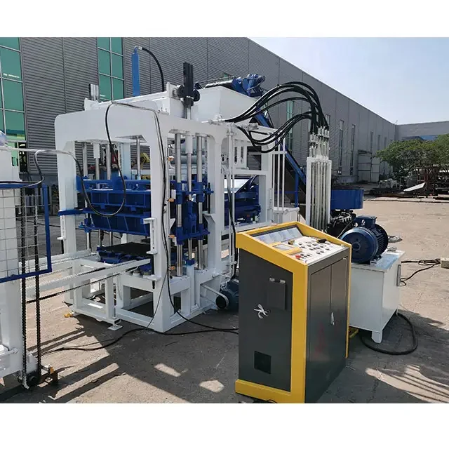
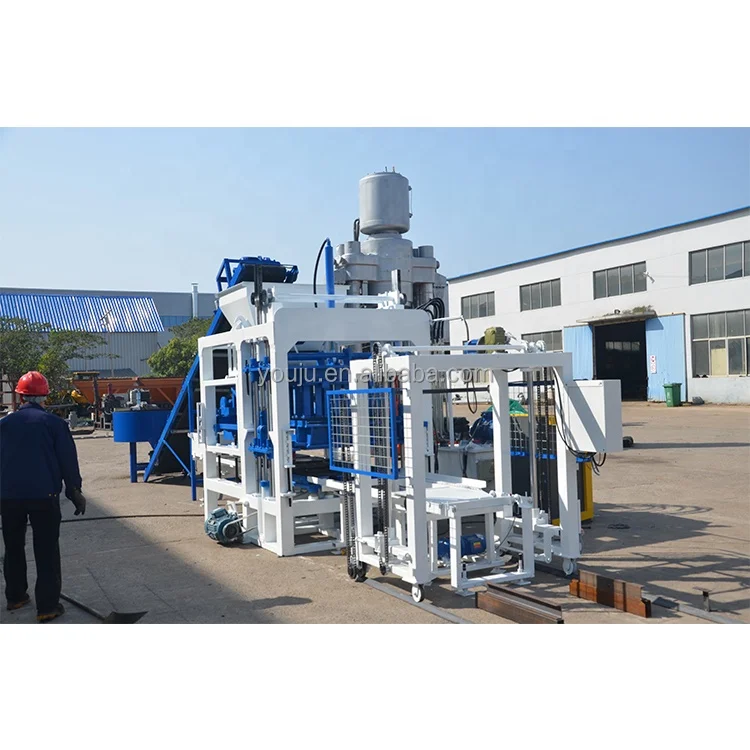
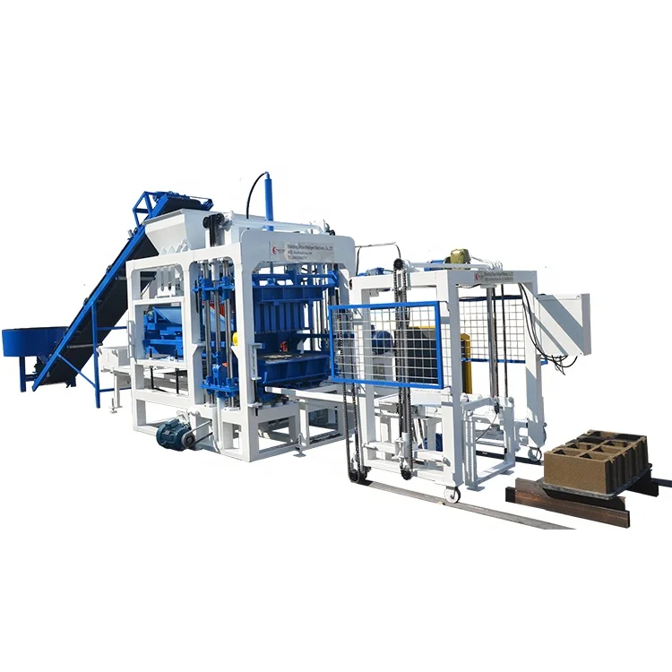
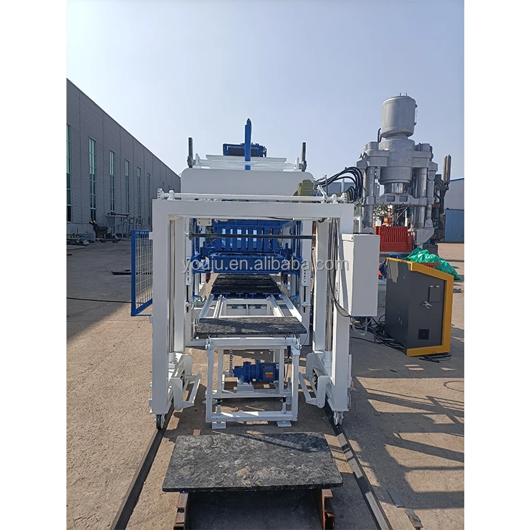
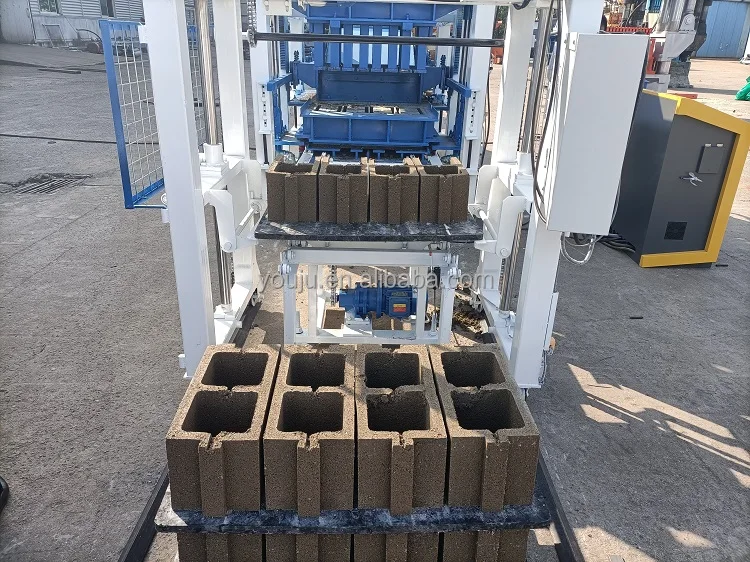
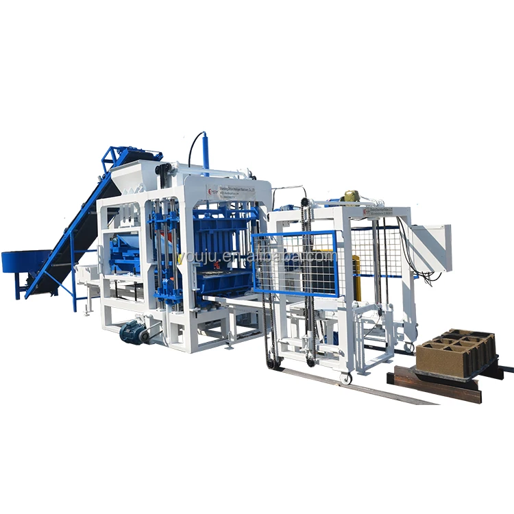
Description
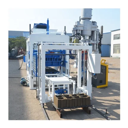
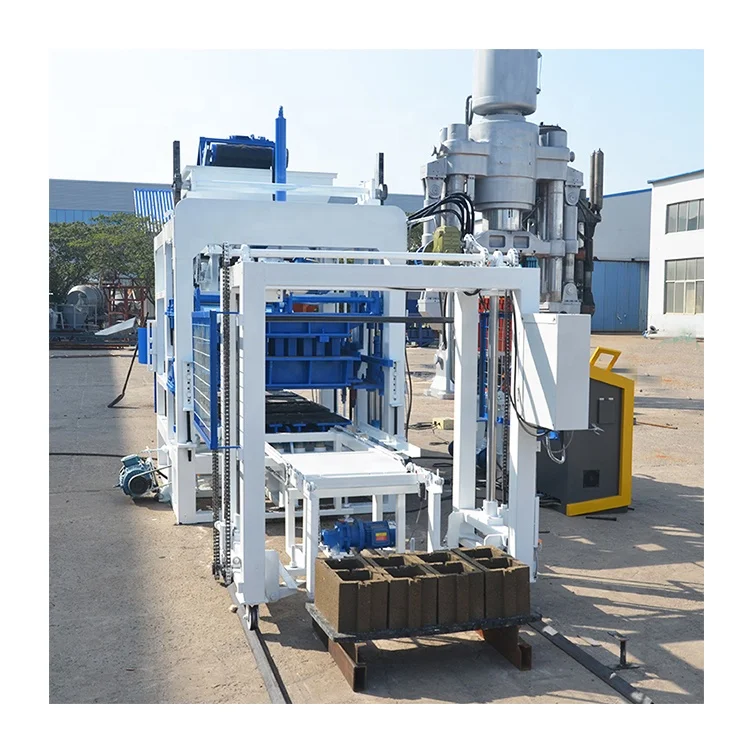
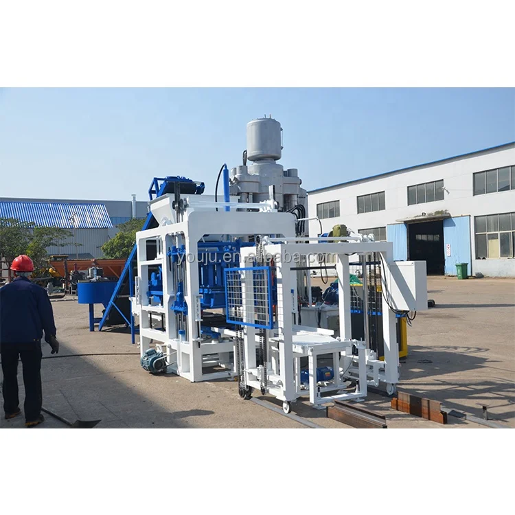
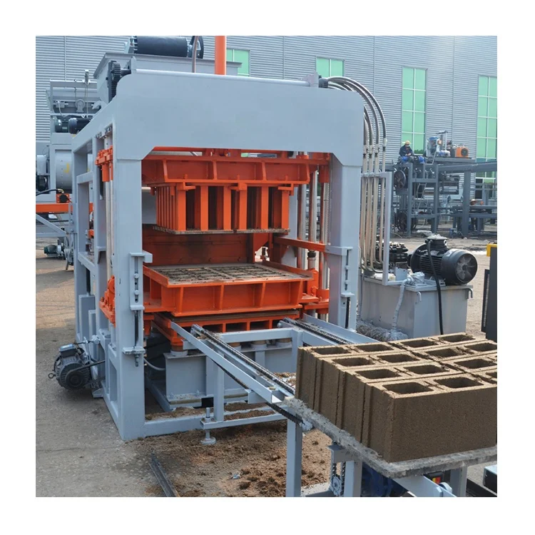
Intelligent Control Architecture — the QT4-18 block making machinery line configures its PLC, frequency converter, and operator interface against the buyer’s actual electrical standard and language before dispatch, preventing the commissioning standstill that occurs when a machine arrives with the wrong default settings.
Technical Specifications
| Parameter | Value |
|---|---|
| Model | QT4-18 |
| Product Type | Automatic Concrete Block Making Machine |
| Overall Dimensions (L×W×H) | 2500×1750×2200 mm |
| Rated Pressure | 16 MPa |
| Vibration Form | Platform Vibration |
| Pallet Size | 950×550 mm |
| Molding Cycle | 18-25 s (basis not stated in source — confirm block format / material / thickness) |
| Overall Power | 27.5 kW |
| Control System | PLC with frequency converter and man-machine interface |
| Electrical Components | Schneider |
| Mould Lifting Mechanism | Double-sided synchronous gears |
| Material Feeder System | Hopper, feeding box, feeding platform, conveyor system |
| Block Receiver | Frame, convey system, idler wheels with motor and reducer |
| Automation Level | Automatic (PLC controlled) |
| Voltage & Frequency | Configurable (to be confirmed with buyer before production) |
| PLC Display Language | Configurable (to be confirmed with buyer before production) |
| Standards | CE |
Application Suitability
| Application | Material or Output |
|---|---|
| Hollow block production for residential and commercial wall construction | Concrete mix with crushed stone, sand, cement, and fly ash |
| Solid block manufacturing for load-bearing structures | Dense aggregate concrete blends with high cement content |
| Paving block production for walkways, driveways, and municipal hardscape | High-strength concrete mixes with fine aggregate and pigments |
| Interlocking brick for retaining walls and landscape projects | Specialized mould profiles with interlocking geometry |
Why the Control Panel Language Matters More Than the Cycle Time
A PLC-controlled automatic concrete block making machine is only as intelligent as the operator who can read its screen.
I once watched a fully equipped QT4-18 sit idle for two days on a site in West Africa because the man-machine interface defaulted to English, and the local crew worked exclusively in French and Twi. The frequency converter was correctly tuned, the mould lifting gears were perfectly synchronized, and the vibration parameters were dialed in — yet the entire production line waited for a language patch. That is the gap between shipping a machine and delivering a working system [NEED_CITE: PLC interface language standards for exported industrial machinery].
The automatic concrete block making machine PLC controlled environment demands that voltage, frequency, display language, and diagnostic readouts all align with the destination site before the machine leaves the factory floor.
Tuning Vibration to Your Mix, Not a Catalogue Default
The frequency converter on this automatic concrete block making machine PLC controlled system allows the operator to adjust vibration intensity directly from the man-machine interface. Different local aggregates — whether river sand, crushed granite, or recycled concrete — absorb vibration energy differently. The ability to tune platform vibration parameters per batch means the operator can match compaction force to the specific mix design available at the site rather than forcing a material substitution.
Mould Alignment and Cycle Consistency Through Synchronous Gears
The double-sided synchronous gear mechanism governs mould lifting and lowering with equal force on both sides. This eliminates the uneven mould seating that causes dimensional variation across a single pallet of blocks. When the PLC manages the gear-driven lift cycle, every mould change follows an identical motion profile, keeping block dimensions within tolerance across thousands of cycles [NEED_CITE: mould alignment tolerance standards for concrete masonry units].
Reading the Specs That Actually Govern Output
The 16 MPa rated pressure and platform vibration system work together to determine block density and compressive strength. Higher hydraulic pressure forces aggregate particles closer while vibration eliminates air pockets — the balance between these two forces defines the structural grade of every block produced. The 950×550 mm pallet size sets the physical boundary for block layout per cycle, and the 27.5 kW overall power rating must be matched against the site’s available supply with adequate headroom. The 18-25 second molding cycle range reflects the spectrum from thin paving blocks to taller hollow blocks, with the exact figure depending on format and mix composition. Schneider electrical components throughout the control cabinet mean replacement contactors and relays follow a globally recognized part numbering system, simplifying local sourcing when the first maintenance interval arrives.
What Happens When Control Configuration Is Left to Chance
When voltage and frequency are assumed rather than confirmed, the PLC and frequency converter can arrive mismatched to the local grid. A 50 Hz motor driven at 60 Hz runs hotter and wears faster, while a 60 Hz motor on 50 Hz loses torque. The result is not an immediate failure but a gradual degradation that shows up as inconsistent block density weeks into production. Similarly, a control panel in the wrong language forces operators to memorize button sequences by position rather than meaning — one miscue during a mould change can drop the assembly onto an unset pallet [NEED_CITE: electrical frequency mismatch effects on industrial motors].
Why Buyers Source This Configuration Here
Block machinery is the single manufacturing focus, so the QT4-18 press, its mould library, pallet specification, and handling equipment are engineered as one matched system rather than assembled from unrelated suppliers. The automation level is selectable — a buyer can start with this PLC-controlled configuration and add automatic stacking and cubing modules later without replacing the core press. Configuration is set against the buyer’s actual mix design and target block format, not a catalogue default. Mould design extends to custom drawings when the buyer’s market demands formats outside the standard range. Installation support includes on-site commissioning and operator training so the crew can navigate the PLC menus from day one.
Documentation & Verification
- Line layout and capacity calculation stating the block format each cycle time assumes
- PLC program documentation with parameter adjustment ranges for operator reference
- Electrical schematic listing Schneider component part numbers for local procurement
- Voltage, frequency, and display language confirmation sheet signed before production
- Factory test record demonstrating cycle repeatability across the buyer’s specified format
- Operation and maintenance manual in the confirmed PLC display language
Installation, Commissioning & Support
- Foundation plan referencing the 2500×1750 mm footprint and vibration isolation requirements
- Dedicated electrical circuit sized for the 27.5 kW overall power draw at confirmed voltage
- Pre-commissioning checklist verifying PLC language, frequency converter parameters, and motor rotation direction
- Operator training covering man-machine interface navigation, mould change procedure, and fault code interpretation
- Wear parts list identifying hydraulic seals and gear components with reorder intervals
- Remote diagnostic module configuration for off-site troubleshooting during the first production months
Before You Request a Quote
To size this automatic concrete block making machine PLC controlled system to your operation, share your target block formats with dimensions, the local aggregate and cement types available, your daily output target by format, and your site’s voltage and frequency standard. Let us know your preferred PLC display language, whether you have existing pallets and curing racks to integrate, and if you plan to expand into automatic stacking at a later stage.
Frequently Asked Questions
Q: How do I verify the real daily output and which block format the cycle time assumes?
A: The 18-25 second molding cycle range covers multiple block formats. Request a capacity calculation sheet that states the exact block dimensions, wall thickness, and mix composition behind each quoted cycle time. Without this format-specific breakdown, a single cycle figure cannot be translated into a meaningful daily production target for your particular product mix.
Q: What PLC display language options are available and how do I confirm before shipment?
A: The man-machine interface supports multiple languages, and the correct one must be confirmed in writing before the machine enters production. This confirmation is captured on a signed specification sheet alongside voltage and frequency. Changing the language after the PLC is programmed requires on-site reconfiguration that delays commissioning and leaves the machine idle.
Q: How does the frequency converter allow vibration tuning for local aggregate?
A: The frequency converter adjusts the platform vibration motor speed from the PLC interface, letting the operator increase or decrease compaction energy per batch. This is essential when local aggregate gradation or moisture content shifts between deliveries. Tuning vibration to each mix prevents under-compacted blocks that fail strength tests and over-compacted blocks that crack during curing.
Q: What is the upgrade path from this configuration to fully automatic stacking?
A: The QT4-18 press and PLC architecture support integration of automatic pallet stacking and cubing modules as a future addition. The control system reserves communication channels for downstream equipment, so adding automation later does not require replacing the core PLC or reprogramming the base cycle logic. Discuss upgrade sequencing during the initial line layout phase.
Q: How do I ensure voltage and control system compatibility with my market’s electrical standard?
A: Confirm your site voltage, frequency, and phase configuration in writing before production begins. The 27.5 kW power system and Schneider components are configured at the factory to match your supply. Arriving with the wrong voltage rating causes motor overheating and PLC instability that may not appear until weeks into operation [NEED_CITE: voltage and frequency standards by export market].